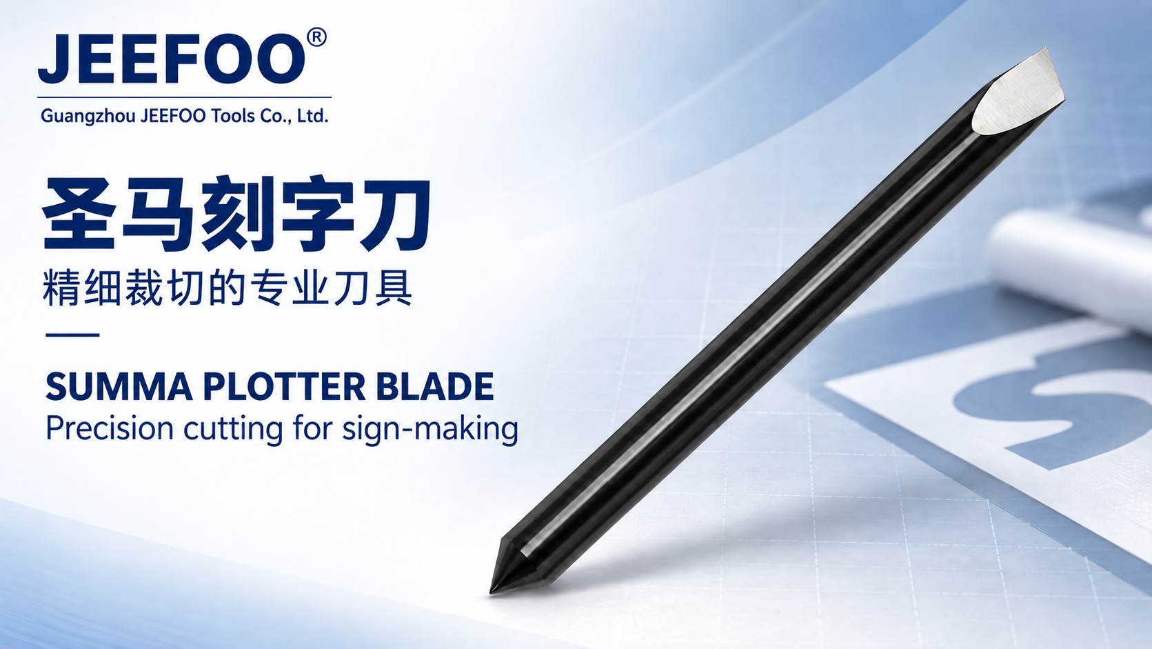
Quick answer: A cemented carbide 3D carving knife is a tapered rotary tool described for three-dimensional corner clearing and chamfering in compatible acrylic, PVC, MDF and medium-hard wood. Tool angle, tip size, cutting width, usable length and carbide grade must match the model, material and spindle. The original listing’s 22 mm blade-width note is a recommendation for some small-format machines, not a universal limit.

What is a cemented carbide 3D carving knife?
The tool follows three-dimensional paths where a square cutter may not reach the required internal angle. It may clear a tapered corner, form a chamfer or refine relief details. A pointed or angled cutter changes feature width as cutting depth changes, so the programmed geometry and Z reference directly affect the result.
Cemented carbide is a tool-material category, not a complete specification. Carbide composition, binder, edge preparation and grinding quality vary. Confirm the manufacturer’s data for the exact cutter before deciding whether it is suitable for a polymer, MDF or wood.
Cemented carbide 3D carving knife geometry
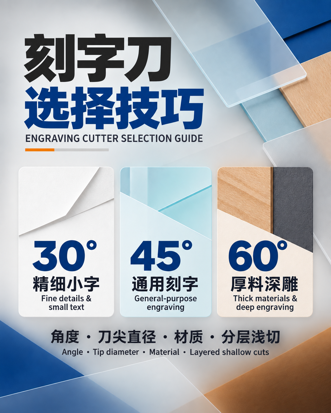
Record the included angle, tip diameter or radius, maximum cutting diameter, usable cutting length and shank size. CAM must represent the actual tool. If a generic V-bit definition uses the wrong angle or tip, the simulated corner and final chamfer can disagree even when the machine follows the path correctly.
Check holder and shank clearance through the full toolpath. A narrow tip may reach a small feature while the upper cutting edge, shank or holder collides with surrounding material. Use simulation, conservative clearance values and a shallow physical test.
Flatness for a cemented carbide 3D carving knife
The source instructions emphasize flatness for both normal and reverse engraving. A warped workpiece or uneven spoilboard changes effective depth. With a tapered tool, that depth error becomes a visible change in line or chamfer width.
Clean the table, support the entire sheet and position clamps or vacuum zones outside the cutting path. Establish the work coordinate from the actual surface. If the machine and software provide a validated surface-mapping process, it may help on demanding work, but it does not replace rigid workholding.
Choosing cemented carbide 3D carving knife width
The listing recommends that some small-format engraving machines use a blade width no greater than 22 mm and suggests a suitable wider tool may improve speed on a large-format machine. Because no specific machine, spindle or cutter model is named, treat 22 mm as contextual guidance rather than a general safety rating.
Choose width from the smallest corner, required chamfer, cutting load, holder clearance and machine capability. A larger edge may remove more material, but it may also erase fine details, increase load or prevent access. The cutter, collet, holder and spindle must all remain within their documented limits.
Materials for a cemented carbide 3D carving knife
The original listing names these materials, but each group contains important variations. Acrylic may be cast or extruded; PVC composition and additives vary; MDF is abrasive and creates fine dust; wood behavior changes with species, grain and moisture. LMT Onsrud’s acrylic routing guidance identifies tooling, programming, machine condition and fixturing as key finish factors.
| Material | Main concern | Check during a test |
|---|---|---|
| Acrylic | Melting, chip rewelding, edge marks | Chip evacuation, sharpness, feed and speed |
| PVC | Heat, burrs, unsuitable ventilation | Exact formulation and supplier instructions |
| MDF | Abrasive wear, fine dust, burning | Extraction, edge condition and fire prevention |
| Medium-hard wood | Tear-out, grain variation, scorching | Grain direction, hold-down and cutting direction |
Seven setup checks before carving
- Define the feature. Record corner angle, depth, smallest detail and required finish.
- Identify the tool. Verify angle, tip, cutting width, usable length, shank and grade.
- Build the real CAM tool. Avoid an approximate visual match.
- Check clearance. Simulate the cutting edge, shank, holder and clamps.
- Flatten and secure the work. Inspect the sheet, spoilboard and support.
- Use supplier starting data. Match speed, feed, pass depth and chip control to the actual material.
- Run a measured sample. Inspect dimensions, line width, heat, chips, sound and surface finish.
Cemented carbide 3D carving knife troubleshooting
| Symptom | Likely checks |
|---|---|
| Uneven line width | Surface flatness, Z reference, runout and work movement |
| Corner remains rounded | Tip size, included angle, access and CAM definition |
| Acrylic smears | Sharpness, chip evacuation, feed, speed and dwell |
| MDF scorches | Edge wear, depth, feed, speed and dust buildup |
| Fine detail disappears | Tip size, blade width, allowance and deflection |
Read more 3D carving cutter guides.
Cemented carbide 3D carving knife safety notes
- Use guarding and material-appropriate dust or chip extraction.
- Stop the spindle before touching the cutter or clearing debris.
- Keep clamps, shank and holder outside the programmed path.
- Never exceed the lowest rated speed in the tool-holding assembly.
- Stop if vibration, sound, heat, load or chip form changes unexpectedly.
Frequently asked questions
Is 22 mm a universal maximum blade width?
No. It is contextual guidance in the original listing. The actual machine and cutter documentation control.
Can a cemented carbide 3D carving knife cut every listed material?
No. Exact carbide grade, geometry, material formulation and machine setup must be compatible.
Why does flatness matter so much?
A tapered tool produces a different width at each depth, so a warped surface makes the result uneven.
Does a wider cemented carbide 3D carving knife work faster?
No. It may raise load or remove fine detail and may not enter a narrow corner.
Conclusion
A cemented carbide 3D carving knife should be selected by verified geometry and machine capability. Treat the 22 mm note as contextual, keep the surface flat and approve the process with a measured test cut.