Quick answer: A T-slot milling cutter is a necked milling tool used after a straight access slot has been prepared. Its wider cutting head enters that slot and removes material from the sides to form an undercut or T-shaped profile. Tool dimensions, material compatibility, machine rigidity, chip evacuation, and manufacturer-supported cutting data must all be checked before machining.

T-slot milling cutter guide
What is a T-slot milling cutter?
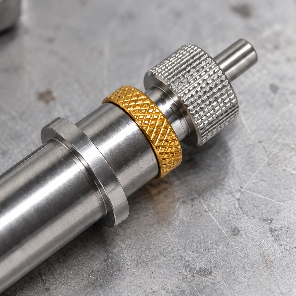
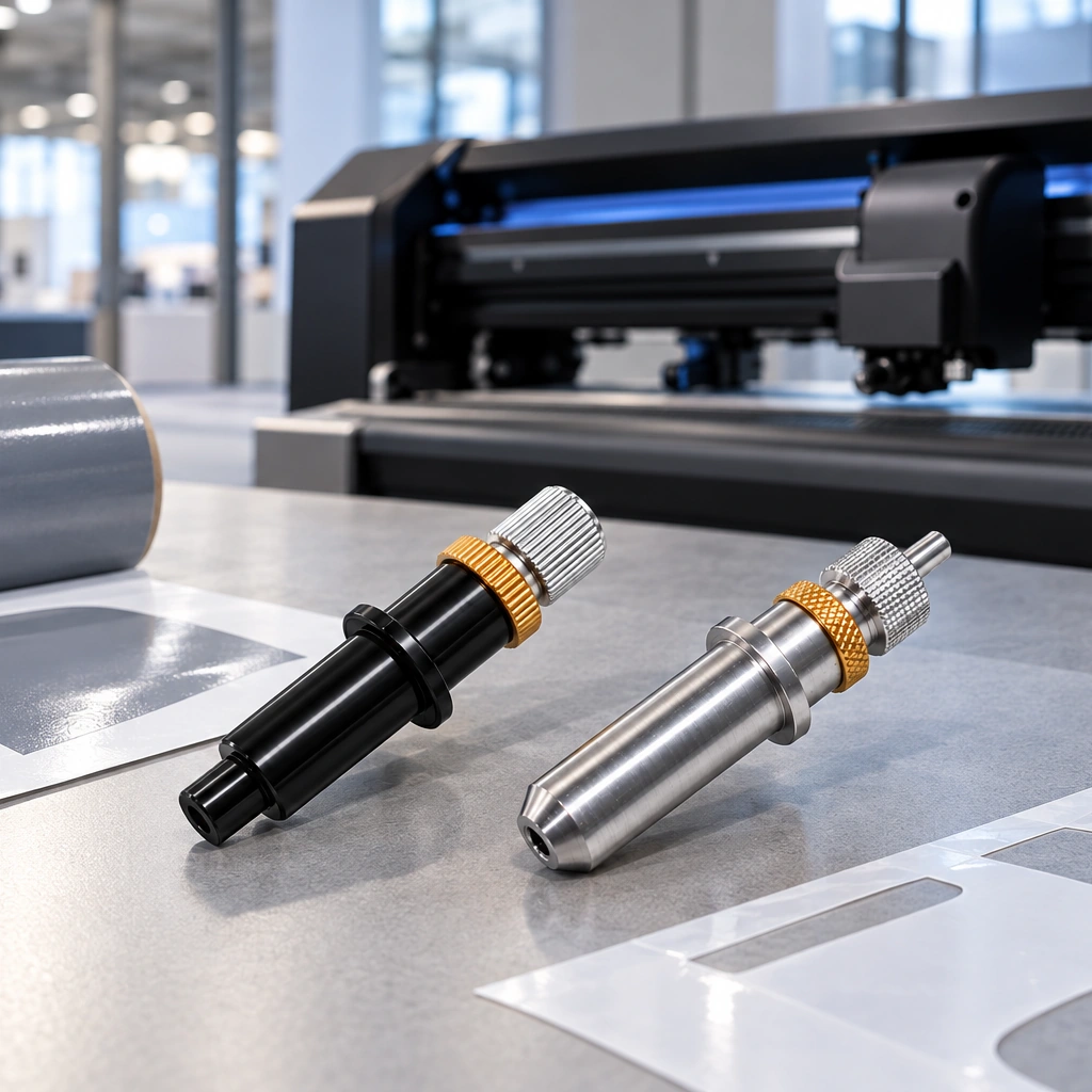
A T-slot cutter normally has a shank, a reduced neck, and a wider cutting head. The neck provides clearance while the head cuts the undercut portion of the feature. The tool may overlap with keyseat or side-milling cutter terminology in some catalogs, but those names are not automatically interchangeable. Confirm the profile, dimensions, and intended operation on the exact manufacturer’s drawing.
A T-shaped groove is usually produced in two stages: first create a straight access slot with an appropriate end mill, then pass the T-slot cutter through that slot at the required depth. Attempting to plunge the full cutter head directly into solid material can overload a tool that was designed for side cutting rather than center cutting.
What can it be used for?
Typical uses include machine-table T-slots, fixture components, sliding fastener tracks, and other engineered undercuts. Suitability depends on the cutter and workpiece. As one verifiable product-family example, Harvey Tool’s official square keyseat-cutter page describes tools offered for standard, deep, and maximum slotting and identifies T-slotting and undercutting operations. That example supports the operating principle, but it does not establish universal dimensions or material limits for every T-slot cutter.
7 specifications to verify before selecting a cutter
- Head diameter: determines the undercut reach and must fit the prepared access slot and feature geometry.
- Cutter width: controls the vertical width of the undercut or keyseat.
- Neck diameter: needs clearance inside the access slot while retaining enough strength for the cut.
- Neck length: must reach the programmed depth without rubbing the shank or holder.
- Shank diameter: must match the correct collet or holder.
- Flute count and edge geometry: influence chip space, cutting forces, and the manufacturer’s recommended feed.
- Tool material, coating, and profile: must suit the workpiece and planned operation.
Do not infer all seven values from a product photo. Obtain the technical drawing or catalog record and enter the real dimensions in the CAM tool library. For example, Harvey Tool lists cutter diameter, cutter width, neck diameter, neck length, flute count, shank diameter, and overall length as separate fields on individual product pages.
Recommended machining sequence
- Review the part drawing and identify the access-slot width, undercut width, depth, corner requirements, and tolerances.
- Machine the straight access slot with a suitable end mill. Provide enough clearance for the cutter neck and a safe entry path for the head.
- Program the T-slot cutter to enter through the open slot, not through uncut stock. Use a lead-in and lead-out that keep sudden engagement under control.
- Apply only the speed, feed, radial engagement, and material guidance supplied for the selected tool. Reduce risk with a conservative test on comparable stock.
- Plan chip evacuation. Chips trapped in an undercut can be recut, raise heat, damage the finish, or load the neck.
- Inspect the finished slot with a suitable gauge or measurement method instead of relying only on the programmed toolpath.
Setup and verification checklist
- Confirm tool, holder, spindle direction, runout, and machine capacity.
- Minimize unnecessary projection while maintaining feature clearance.
- Check workholding and simulate the holder, neck, head, clamps, and fixture.
- Verify that the prepared slot is wide and deep enough for safe entry.
- Use coolant, air, or extraction only as appropriate for the workpiece, tool, and machine instructions.
- Stop if vibration, chip packing, abnormal sound, excessive heat, or visible deflection occurs.
The original short description stated that a T-shaped tool can “maintain cutting performance at high temperatures.” That is not a safe universal claim. Heat resistance depends on substrate, coating, edge geometry, workpiece, cutting data, and coolant strategy, so it must be confirmed for the exact product.
For related cutter and engraving-tool information, visit the Jeefoo cutting-tool article hub.
T-slot milling cutter FAQ
Can a T-slot cutter make the entire groove in one plunge?
Usually the access slot is machined first. Whether a specific cutter can ramp, plunge, or center cut must be confirmed from its manufacturer’s instructions.
Is a T-slot cutter the same as a keyseat cutter?
The terms can overlap in catalogs, but geometry and intended use vary. Match the technical drawing and operating description to the required feature.
How should feeds and speeds be chosen?
Use data for the exact cutter, material, coating, diameter, flute count, holder, and machine. This article does not provide a universal RPM because the required product and machining details are not specified.
Why is neck clearance important?
The reduced neck must pass through the access slot without rubbing, while the cutting head reaches the undercut. Insufficient clearance can cause collision, heat, and tool failure.
Conclusion
A T-slot milling cutter is best treated as a dimension-specific undercutting tool, not as a generic “T knife.” Prepare the access slot, verify every relevant dimension, follow product-specific cutting data, control chip evacuation, and inspect the completed feature before approving production.