Quick answer: Cutting tool types can be classified in several useful ways. One practical three-part framework groups them as general-purpose machining tools, form tools, and generating tools. The distinction depends on how cutting motion and edge geometry create the finished surface. This is an explanatory framework rather than a claim that every engineering standard uses only these three categories.
Table of contents
Cutting tool types: three-category summary
| Category | How geometry is produced | Typical examples |
|---|---|---|
| General-purpose machining tools | Relative tool and workpiece motion produces the surface | Turning tools, drills, boring tools, milling cutters, reamers, saws |
| Form tools | The cutting edge carries all or part of the required profile | Form turning tools, broaches, taper reamers, thread-form tools |
| Generating tools | Coordinated motion generates a tooth or related profile | Hobs, gear shaper cutters, shaving cutters, bevel-gear cutters |
Major industrial training resources also organize metal cutting by processes such as turning, milling, drilling, boring, threading, and toolholding. For example, Sandvik Coromant’s metal-cutting education covers these process families. The framework below adds another lens: whether the result comes mainly from motion, edge form, or a generating relationship.
1. General-purpose machining tools
In this group, the final surface is created primarily by controlled relative motion between tool and workpiece. A turning tool removes material as the workpiece rotates. A milling cutter uses one or more rotating teeth while the cutter or workpiece feeds along a programmed path. A drill produces a hole through rotation and axial feed, while boring tools enlarge or refine an existing hole. Reamers improve hole size and finish, and saws separate material with repeated cutting teeth.
These tools are versatile because the same basic tool family can produce many dimensions and shapes by changing the machine path, setup, insert geometry, diameter, or operating parameters. However, “general-purpose” does not mean universal. Tool material, coating, edge preparation, chip control, rigidity, coolant strategy, cutting speed, feed, and depth of cut still need to match the workpiece and operation.
2. Form tools
A form tool has a cutting profile that corresponds to all or part of the required workpiece profile. Instead of generating every detail through a long sequence of motion, the tool edge transfers its geometry into the workpiece. Examples include form turning tools, form milling cutters, broaches, taper reamers, and tools designed for particular grooves or thread profiles.
Form tooling can produce a repeated profile efficiently, which is valuable in stable production. The tradeoff is specialization: a profile change may require a different tool, regrinding method, inspection plan, or setup. Cutting forces may also be distributed across a wider engaged edge. Process planning therefore has to consider machine power, workholding, chatter risk, chip evacuation, dimensional tolerance, and how tool wear changes the transferred profile.
3. Gear-generating and toothed-profile tools
Generating tools produce a profile through a defined relationship between tool shape and coordinated motion. Gear hobbing and gear shaping are familiar examples. In hobbing, the rotating hob and gear blank move in a synchronized relationship that progressively generates the tooth form. Gear shaper cutters, shaving cutters, and some bevel-gear tools use other controlled relationships to create or finish toothed surfaces.
The important point is that the finished tooth is not always a simple direct copy of one stationary cutting edge. Machine kinematics, tool geometry, indexing, helix or pressure-angle requirements, blank dimensions, and synchronization all contribute. Tool selection must therefore be based on the gear system, module or diametral pitch, tooth count, quality target, machine capability, and finishing allowance.
How to select among cutting tool types
- Define the feature: Identify whether the job requires a simple surface, hole, repeated profile, thread, groove, or generated tooth form.
- Identify the process and machine: Confirm available spindle, axes, toolholding, rigidity, power, coolant, and synchronization capability.
- Specify the workpiece: Record material grade, hardness, heat treatment, stock condition, and interruption level.
- Set the quality target: Define tolerance, surface finish, edge condition, profile accuracy, and inspection method.
- Compare economics: Balance cycle time, tool cost, changeover, regrinding, inventory, and expected batch size.
- Validate safely: Use manufacturer cutting data as a starting point, run a controlled trial, inspect the part, and adjust within machine and tool limits.
Common classification overlaps
Real tools can fit more than one description. A form milling cutter is still a milling cutter, but its profile makes it a form tool in this framework. A gear hob has multiple cutting teeth, yet its defining feature is the generating relationship. Indexable and solid tools may appear in any process family. Likewise, single-point versus multi-point, solid versus indexable, and high-speed steel versus carbide are separate classification axes, not contradictions.
Frequently asked questions
Is this three-part classification an ISO standard?
This article presents a practical teaching framework. It should not be cited as the only universal or ISO-mandated classification. Standards and manufacturers may classify tools by process, material, geometry, mounting, or application.
Are drills and reamers general-purpose tools?
They are commonly grouped with holemaking tools and fit the general-purpose category here because controlled rotation and feed create the hole. A specially profiled reamer may also be discussed as a form tool.
What makes a form tool different?
Its cutting edge contains all or part of the intended workpiece profile, so edge geometry directly controls the repeated shape.
Why are hobs called generating tools?
The gear tooth form develops through synchronized relative motion between the hob and blank rather than through a single stationary edge that exactly matches the complete tooth space.
Which cutting tool type is best?
There is no universal best type. The correct choice depends on feature geometry, workpiece material, machine capability, tolerance, surface finish, batch size, safety, and total cost.
Cutting tool types visual example

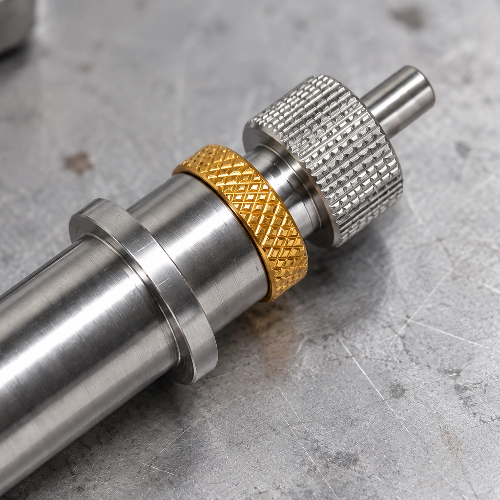
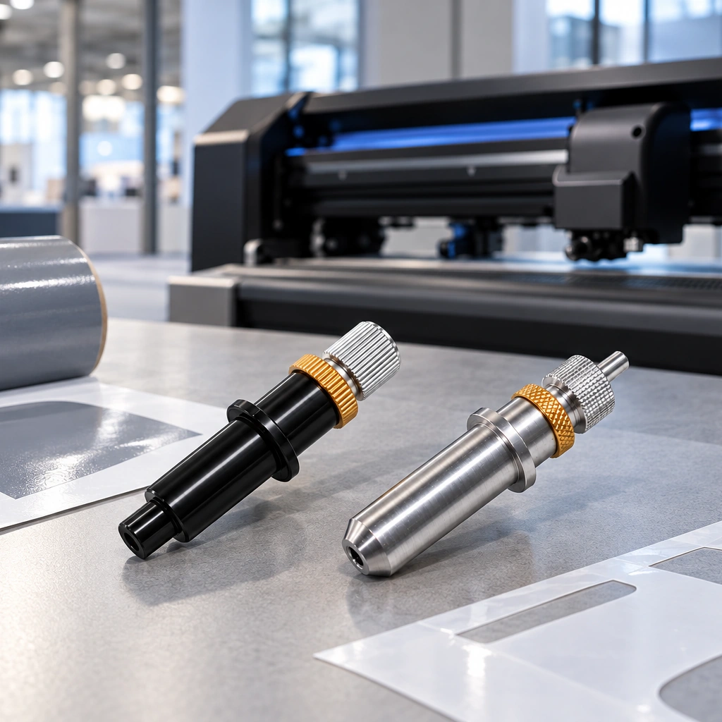
This carbide plotter blade is one narrow example within the wider universe of cutting tool types. Its application, edge angle and holder differ from turning, milling, drilling, form and gear-generating tools. The broader classification still depends on the process and on how motion and edge geometry create the required feature. When documenting cutting tool types, record both the classification lens and the actual manufacturing operation.
Conclusion
Cutting tool types are easiest to understand when the classification purpose is stated. General-purpose tools rely mainly on machining motion, form tools transfer a defined edge profile, and generating tools combine geometry with coordinated motion to create toothed or related surfaces. Use this framework alongside process-specific manufacturer guidance and the requirements of the actual machine and workpiece.
Browse more cutting-tool articles for related manufacturing information.