快速结论:米马克刻字刀设计原理的核心,是让偏心安装的刀尖在拖动过程中随走刀方向自行转向,并通过刀尖外露量、切割压力、速度与设备中的偏移量设置完成薄膜半切。刀片角度、刀柄尺寸和兼容机型必须以具体刀片、刀座及 MIMAKI 设备说明为准,不能只凭“30°、45°或60°”标签判断。
米马克刻字刀设计原理:偏心拖刀结构
拖刀式刻字刀的刀尖并不与刀座旋转中心完全重合。设备带动刀座移动时,切削阻力会使刀尖朝向当前运动方向;走刀方向改变后,刀尖会围绕刀座中心转向,再继续沿新方向切割。这种结构不需要每次转弯都由独立电机主动旋转刀片,适合在不干胶、标签膜和其他兼容薄膜上形成连续轮廓。
偏心结构能否正常工作,取决于刀片在刀座内是否转动顺畅、刀尖是否完整、刀柄与刀座是否匹配,以及软件或设备中的刀具偏移量是否正确。若刀座内有残胶、灰尘或碎屑,刀片转向可能变慢,转角处就可能出现圆角、翘角、拉膜或闭合不准。
“偏心量”不是所有米马克兼容刀片都相同的固定值。不同刀片、刀座和设备可采用不同参数,设置前应查阅对应型号的刀具说明或设备手册。MIMAKI 官方试切故障说明也指出,转角变圆时需要核对刀座中心到刀尖的距离,并让设备中的 OFFSET 值与所用刀具匹配。
30°、45°和60°刀尖怎样理解
市场上常用 30°、45°、60°区分刻字刀刀尖几何,但角度标签本身不能独立决定材料范围。不同厂家的标注方法、刃长、尖端半径、偏移量、硬质合金牌号和研磨质量可能不同。选型时必须同时核对刀片型号、刀座、材料厚度、图形细节和设备要求。
30°刀尖:偏向精细轮廓
较小角度通常用于较薄材料、细线和小字,因为其有效切入区域相对集中。实际效果仍受刀尖外露、压力、速度和材料胶层影响。过度追求锋利并不能解决所有细节问题;若刀尖露出过长,反而可能增加断尖、划伤底纸或转角变形的风险。
45°刀尖:常见通用选择
45°常被作为日常薄膜切割的通用起点,在锋利度与刃口支撑之间取得折中。它是否适合某一种即时贴、热转印膜或标签材料,仍要通过小范围试切确认。材料表层、胶层和底纸结构不同,即使名义厚度接近,所需压力也可能不同。
60°刀尖:用于需要更深切入的场景
较大角度常被用于较厚或结构更复杂的兼容材料,但不能简单理解为“越厚就一定用60°”。刀刃长度、材料硬度、图形大小、转角半径和设备能力都会影响结果。切换刀尖角度后,应重新检查偏移量、外露量、压力和速度,而不是沿用上一把刀的全部参数。
刀尖外露量与半切设置
半切的目标,是切透面材并尽量保持底纸完整。正确做法不是单独提高压力,而是让刀尖外露量接近实际需要,再用设备压力完成切割。MIMAKI CG-AR 系列官方操作说明建议根据刀具和材料调整外露量,并通过试切检查;其说明还提醒,刀尖伸出过多可能损伤设备。
可参考 MIMAKI 官方刀尖外露量调整说明。该页面针对特定系列,不能直接代替其他型号的手册;它提供的是调整逻辑和安全提醒,而不是所有设备通用的数值。
建议的试切顺序
- 确认材料与刀具。记录面材、底纸、刀片型号、刀座和设备型号。
- 缩短刀尖外露。先让刀尖只露出完成切割所需的最小长度,避免把过长外露当作“更锋利”。
- 从保守压力开始。使用设备或材料供应商建议作为起点,不清楚时不要直接使用高压力。
- 运行内置试切。检查小图形能否完整剥离,同时观察底纸是否只留下轻微痕迹。
- 一次只改一个变量。先调整外露或压力,再检查速度和偏移量,避免同时大幅改变多个参数。
- 记录可复现设置。将材料批次、刀片型号、压力、速度和偏移量写入工艺记录。
如果面材没有切透,可检查刀尖是否磨损、刀座是否松动、速度是否过高、外露是否不足,再小幅调整压力。若底纸被切穿,则应优先检查压力过大或刀尖外露过长。若拐角圆钝或翘起,应同时检查偏移量、外露量和压力,不能只靠继续加压处理。
如何核对米马克刻字刀的兼容性
| 核对项目 | 为什么重要 | 建议证据 |
|---|---|---|
| 设备型号 | 不同系列的刀座、工具条件和菜单可能不同 | 设备铭牌与对应官方手册 |
| 刀座型号 | 决定刀柄是否能正确夹持和转动 | 刀座标识、供应商尺寸图 |
| 刀片型号与杆径 | 外观相似不代表尺寸和偏移量一致 | 产品规格页或实测尺寸 |
| 刀尖角度与偏移量 | 影响转角与细节表现 | 刀片说明和设备 OFFSET 设置 |
| 材料结构 | 面材、胶层和底纸共同决定切割条件 | 材料技术资料与试切记录 |
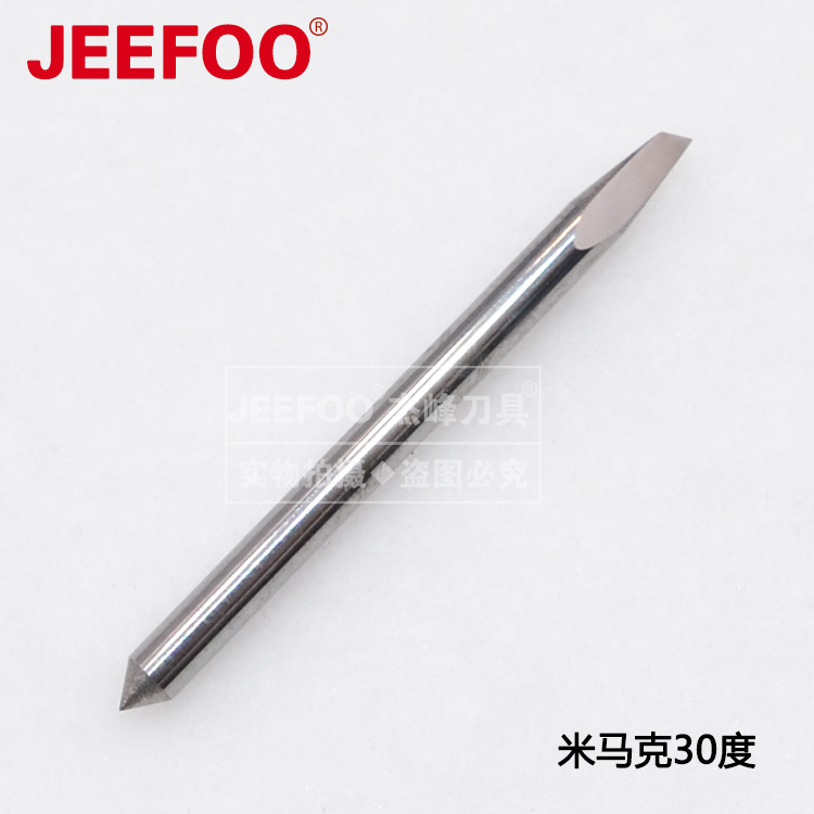
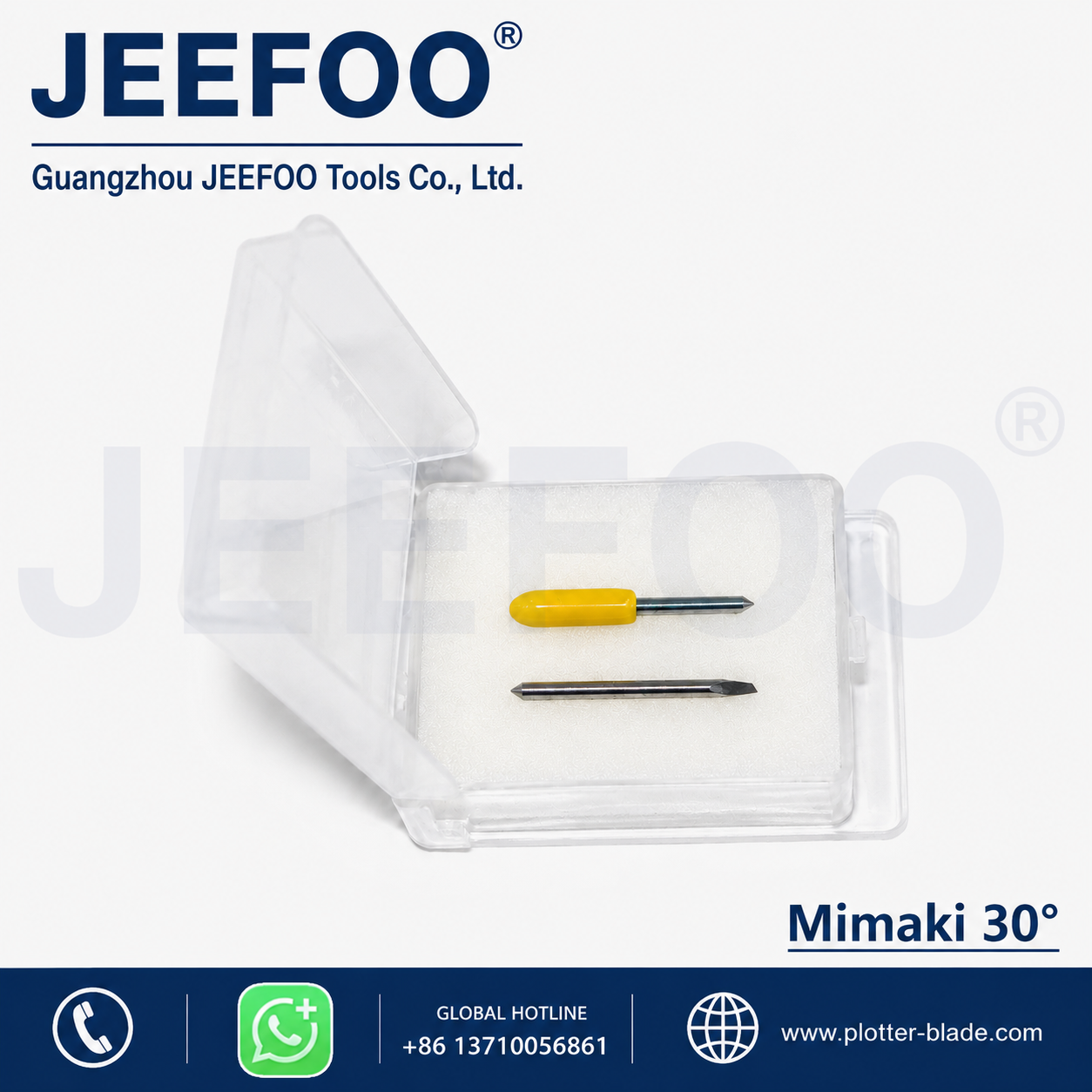
网站图片中的刀片可以帮助识别外观,但不能单独证明与某一台机器兼容。下单或安装前,应将设备完整型号、现用刀座照片和原刀片尺寸与供应方核对。若无法确认规格,不应强行装入刀座。
更多刀具结构、使用与选型内容可浏览本站刻字刀技术文章目录。站内文章用于提供通用判断框架,具体操作仍以设备制造商和刀具供应商针对型号给出的资料为准。
使用与安全检查
- 关机或按设备要求停止运动后,再拆装刀片与刀座。
- 刀尖锋利且硬质刀尖通常较脆,拆装时使用合适工具并避免侧向碰撞。
- 清理刀座残胶和碎屑,但不要使用会损伤密封或轴承的清洁方式。
- 确认刀座已固定、刀尖外露合理、材料压轮位置正确,随后再执行试切。
- 不得用手接触运动中的刀头,也不要在设备运行时清理材料。
- 出现异常噪声、拉膜、连续断尖或刀座发热时,应停止并排查,而不是继续加压。
常见问题
米马克刻字刀为什么采用偏心刀尖?
偏心使拖刀在运动时能受切削阻力带动而转向,从而跟随路径切割。它需要正确的刀具偏移设置和顺畅转动的刀座才能获得正常转角。
30°、45°、60°中哪一种最好?
没有通用“最好”。较小角度常用于精细薄膜,45°常作为通用起点,较大角度可用于需要更深切入的兼容材料;最终应按具体刀片规格、材料和试切结果选择。
为什么换新刀后反而切穿底纸?
新刀刃更锋利,原来的压力和外露量可能过大。应减少刀尖外露或压力并重新试切,同时确认材料批次和底纸结构是否变化。
出现圆角一定是刀片磨损吗?
不一定。圆角还可能来自 OFFSET 不匹配、刀座转动受阻、速度过高、外露或压力过大以及图形半径超出工艺能力。应逐项检查并一次只改一个变量。
可以直接套用网上的压力数值吗?
不建议。压力受设备、刀具、材料、底纸和刀尖状态影响。应使用对应型号资料作为起点,并通过设备试切验证。
结论
米马克刻字刀设计原理并不是单一角度或一个固定偏心数值,而是偏心拖刀结构、刀座转动、刀尖几何、外露量、压力、速度与 OFFSET 设置共同作用的结果。可靠的做法是先确认设备、刀座和刀片规格,再按官方逻辑进行小范围试切,保留底纸完整并记录可复现参数;不确定的尺寸、材料成分和兼容性不能根据外观推断。
English technical summary: Mimaki-compatible drag-knife setup
Mimaki-compatible cutting blade design and setup
This English reference summary explains the same verified setup logic for readers who search in English. A Mimaki-compatible cutting blade commonly works as a passive drag knife. The cutting tip is offset from the rotation center of the holder, so cutting resistance turns the blade toward the travel direction. When the carriage changes direction, a clean holder allows the blade to rotate and follow the new path. Correct corner quality therefore depends on the relationship among the physical blade offset, the holder, and the OFFSET value used by the cutter.
Blade angle is only one selection factor
Labels such as 30 degree, 45 degree, and 60 degree describe a nominal tip geometry, but they do not prove machine compatibility or predict results by themselves. A smaller angle is often considered for fine details in thin films. A 45 degree blade is commonly treated as a general starting point. A larger angle may be considered when a compatible material requires deeper penetration. Actual selection must also consider the blade model, shank dimensions, edge length, tip radius, holder, material construction, adhesive, liner, and the smallest corner in the design.
Do not infer shank diameter, carbide composition, offset distance, or compatible machine series from a product photograph. Obtain those values from a specification sheet or direct measurement, and compare them with the tool holder and the operation manual for the exact cutter model.
Control protrusion before adding force
For kiss cutting, the goal is to cut the face film while preserving the liner. Extend only enough blade to complete the cut. Excessive protrusion increases the risk of cutting through the liner, damaging the cutting strip or machine, breaking the tip, and lifting corners. Pressure should refine a correctly exposed blade, not compensate for a blade that extends too far or a worn edge.
MIMAKI’s CG-AR operation guidance instructs users to adjust blade protrusion for the cutter and sheet, verify performance with a test cut, and avoid excessive protrusion. The published values and adjustment mechanism belong to the documented series; another machine may use a different holder or procedure. Always use the manual that matches the machine nameplate and firmware context.
A repeatable test procedure
- Record the full cutter model, holder identification, blade model, and sheet construction.
- Inspect the tip and make sure the blade rotates freely in a clean, undamaged holder.
- Set the minimum practical protrusion rather than exposing the full edge.
- Begin from the manufacturer’s documented tool condition or a conservative verified starting point.
- Run the machine’s test pattern and weed the face film to check closed paths and small corners.
- Inspect the liner. A deep cut indicates too much protrusion, excessive force, or both.
- If corners are rounded, check OFFSET, holder rotation, speed, protrusion, pressure, and the physical limits of the design.
- Change one variable at a time and record the result so the setup can be reproduced.
Troubleshooting observations
An uncut section does not always mean that pressure must increase. The edge may be dull, the holder may be loose, the blade may not rotate, the speed may be too high, or protrusion may be insufficient. A liner cut does not always require a new blade; reduce protrusion and pressure, then repeat the test. Rounded corners can result from an incorrect offset value or a contaminated holder. Lifted corners can result from excessive protrusion, force, speed, or an unsuitable combination of blade geometry and material.
Replace a damaged blade and stop using a holder that has worn seating surfaces or abnormal play. Keep hands away from the moving carriage, stop the machine before installing a blade, and follow the manufacturer’s guarding and maintenance instructions. This bilingual summary does not authorize a specific blade for a specific Mimaki model; compatibility must be confirmed with traceable specifications.